


You’ve made it this far — and by now you’re starting to see what it really takes to make your product manufacturable.
From defining those important Critical to Quality (CTQ) features, mapping your process flow, developing datum schemes and conducting tolerance stacks to test the feasibility of each CTQ.
By the end you should have a Red, Amber, Green status of all your dimensional CTQs. For those not attaining Cp > 1.33/1.67 you know to re-examine the what-if process of assembly and part manufacture again or specify 100% inspection and rework procedures.
Now you are almost ready to begin manufacturing your product, whereby your Manufacturing Design Department develop and execute the Design for Manufacture (DFM). Following the sequence laid out in the tolerance stack, using datum features to guide their tooling design.
Design and Purchasing onboard suppliers to manufacture key parts while your Quality Department develop inspection methods to detect drift in manufacturing, as well as the resolution steps necessary to root cause and correct the associated deviation.
However, it is worth taking time out to explore a topic that does not fit neatly within the A-to-Z process being laid out. These are the design strategies that you can employ to make your product manufacturable.
🧠 What Are These Design Strategies?
If you were to design purely to optimize variation, you would have fewer more complex parts, less assembly operations, and precision fits. However, there are other considerations beyond variation, namely how you will tune production to compensate for mean shifts.
In addition, there are ways to de-sensitize your design to variation. However, they might leave your industrial design department thinking you are overstepping your jurisdiction by suggesting them.
Considering the less contentious ones first, these can be broadly separated into adjustability, design gaps, floats and clearances, and post-processing. These strategies can be used in isolation or in combination, to achieve the optimal manufacturing process.
🔧 Adjustability
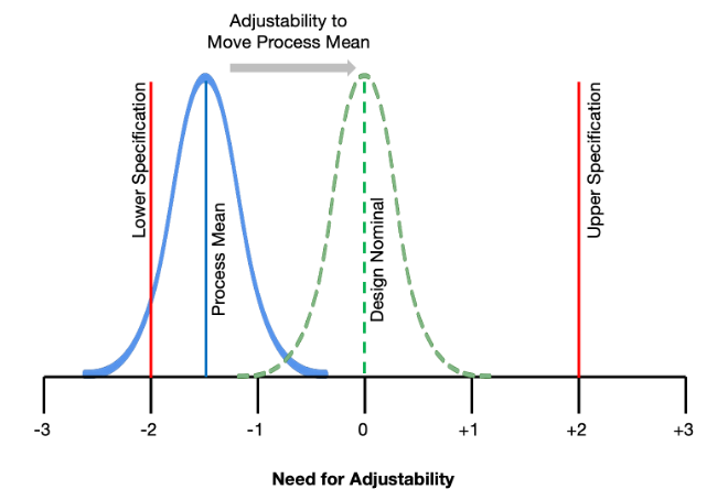
Mean-shifts are deviations away from the perfect design nominal on average, rather than variation, which can be considered as the noise.
It is your job to move that average back to where it is desired in manufacturing, which may not necessarily be back to nominal, and for that you need adjustability.
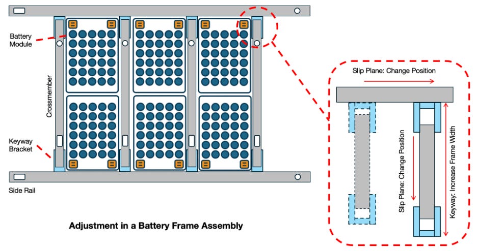
Let’s take a battery frame as an example. It will have multiple CTQs, including fitment of battery modules, mounting to the vehicle body, and routing locations for coolant interfaces.
If a shipment of modules came in, whose mounting locations were off-center, you need a way to quickly compensate for this without affecting other CTQs.
By breaking down the assembly into components such as cross-members and side-rails. Then by using a combination of keyways and slip planes, you can independently adjust the location of these components in minutes.
Locations can be adjusted, by fine increments, through adding or removing shims in your tooling datum surfaces and locating pins, compensating for the mean shift in your battery module.
Further, by just adjusting the cross-member, the peripheral locations on the side-rail which line-up with the chassis mounting locations are unaffected. Therefore, by planning your adjustability effectively, means limiting the quantity of CTQs affected by any one adjustment.
Typically, the further you move downstream, the more you want to consider how you can incorporate methods of simple and quick compensation. It is here, where tolerance stacks are at their longest, and multiple mean-shifts culminate.
As well as this ability to adjust, you need a way to regularly measure the output from these processes, complemented by a steady stream of data from upstream, so that adjustments are made from a position of knowledge, not reaction.
At this point, some of you may be asking why giga castings then?
And you’re correct, on the surface these mega castings appear to be limiting adjustability. But there are other ways to manage mean-shifts and variation, and we will come back to these shortly.
📐 Design Gaps, Floats & Clearances
A key enabler for adjustability, are incorporating design gaps, floats and clearances, to provide space for both variation and adjustment to be absorbed, pushing it away from sensitive areas of the design.
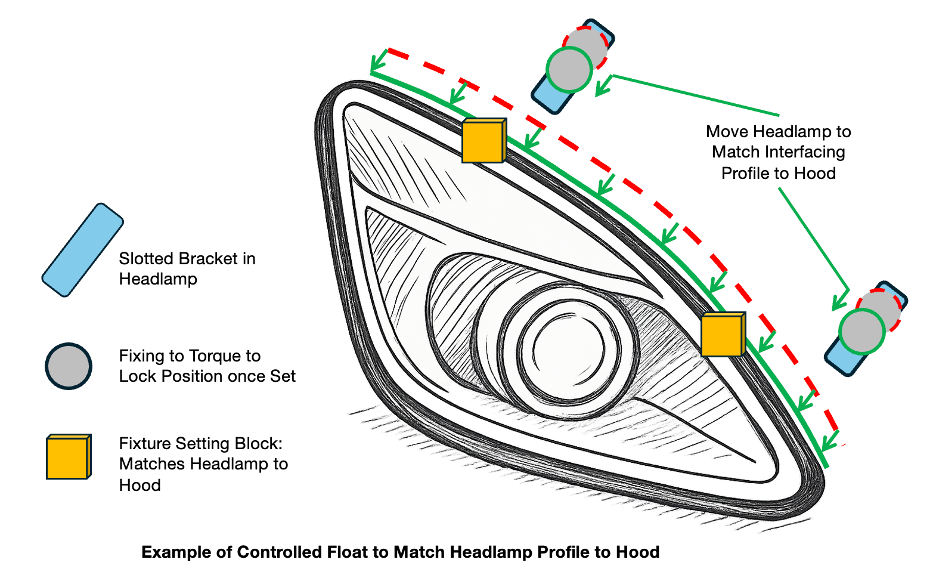
Take a headlamp as an example. If it was precisely pinned to the vehicle body, the fit to hood and fender would be locked right where variation and mean-shifts are largest. The odds of a perfect cosmetic match are extremely low.
Instead, you can utilize oversized holes, slotted brackets, or floating mounts to allow for controlled movement of the headlamp during install.
You can then use a fixture, which is adjustable to correct for any drift, to position the headlamp to achieve the required gap and profile to hood and fender. The mounting points, which incorporate this float or clearance, are then torqued to set the lamp in position.
The result, a clean visual match despite upstream variation. Instead, error is concealed under the hood away from any interfacing areas.
As well as floats and clearances, small gaps in the CAD, which when it comes to reality aren’t there, can also be used to absorb variation from two complex sub-assemblies.
For example, when you are trying to join the side of your car to the floor, each sub-assembly may have 50 or more parts, that is an extremely long tolerance chain to manage.
Therefore, you want your tooling to set the relationship between these vast subassemblies, and for that you need a design gap to provide free space to accommodate variation because of poor part quality, weld draw, or adhesive thickness.
Your tooling will then close-up any gap that remains, allowing the assembly to be welded in the correct set position and orientation.
If a gap did not exist in your design, the long tolerance chain will cause parts to clash, introducing stress into the assembly. This stress causes the completed assembly to spring out of the tooling, losing the accuracy you painstakingly just set . . . sigh.
🛠 Assembly Post-Processing
Just as post-processing in computing refines a raw digital output into something polished and ready for use.
Manufacturing post-processing involves refining key interfaces and joining locations at the end of assembly steps, rather than performing multiple operations upstream on individual parts.
The advantage, well these dimensions can be formed, typically through machining or piercing operations in one go, using the assembly datum scheme, giving more control over their relationship and making them more relevant to the downstream operation.
Earlier, I mentioned giga-castings, because I knew you were thinking about it when we were discussing making all these adjustments on these individual parts.
Well, having never worked with giga-castings, I would expect it makes use of this post-processing methodology, by in effect combining several parts in a single casting, allowing all post-cast machining to be done in one or very few cells.
This enables precise control of key fitment locations, such as fascia or fender interfaces, that would otherwise be distributed across multiple components.
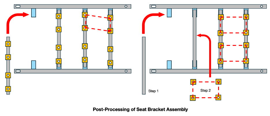
To illustrate further, the potential advantages of this method, I will extend our previous battery frame example. It might be that downstream you need to attach seats to the battery frame, as it forms the structural part of the vehicle floor.
You could weld the brackets that the seat will screw into onto the individual crossmembers and then weld the crossmembers together with the side rails to form the frame. However, this will mean the relationship between the four seat brackets are not directly set.
Further, if you moved the cross member to correct your previous issue with the battery module fitment. There is potential that you inadvertently cause a seat fitment issue because you have directly changed the relationship between the brackets.
Now, if you directly assembled all the seat towers into a fixture and assembled to the post-frame welding using a reference on the crossmember, the relationship is directly set.
Then, if you introduced a slip plane between the crossmembers and brackets, then any reasonable adjustment in the crossmember would not affect seat fitment, giving you independent control over your CTQs.
🤔 So Why Don’t We Do Everything This Way?
Well, the more complex the post processing, the more expensive it becomes.
For a large part such as a front fascia, fitment and datum locations will span over several components of the vehicle body.
Therefore, a metrology equipped cell is needed to measure the assembly datum points, to construct the fascia sub-datum coordinate frame used to guide the piercing tool that forms the fitment locations.
Further, the more complex the assembly, the more effort you need to make in stabilizing your assembly reference points that you will use in your metrology cell. If the relationship between the datum features is not stable, then the end result will be highly variable.
For this reason, it can be difficult to tune these post-processing cells during commissioning and ramp, where the upstream parts and assemblies are still being dialed in. This means that the ground underneath the sub-datum features is constantly moving.
A certain level of process maturity is required for these cells to be effective, and it is why start-ups and scale-ups can struggle with these cells, especially when they are launching and ramping at speed.
That is why it is best to bring these cells online later and not be fully reliant on them at the start of production.
Net Form and Pierce Post-Processing Method (Tünkers Maschinenbau GmbH)
💡 Suggestions That Make Design Go Hmmmm….
Now the methods to manage variation just discussed, may have engineering worrying about correlating crash simulation, or whether the clamp load of a washer will be sufficient with a certain clearance hole size.
But they are possibilities to be discussed and iterated over, until the right trade-offs are made for the build and product integrity.
Now the following methods of managing variation are purely cosmetic, concepts like slip planes transfer over, while others are new.
Being cosmetic options, whether they are utilized, are at the discretion of your Industrial Design Department because they affect the design language of the product.
However, if you have the chance to sit in a styling review and feeling brave, you can offer one or more of the following suggestions:
Offset Surfaces: By deliberately offsetting one interfacing surface to another it desensitizes the user to any change in relationship between said surfaces, compared to if the interfaces matched, requiring less control in production.
Slip Planes: Rather than locking in a part by having cosmetic interfaces on both its edges. If one edge was designed to be a slip plane, it allows the gap at the other edge to be adjusted to achieve ideal fit, without fear of affecting another interface.
Minimizing Matching Features or Interfaces: Minimizing the number of interfacing parts that come together in a visually sensitive area reduces the number of individual controls needed to be managed in production.
Disguising Interfaces: Concealing the interface through use of blackout at the interfacing area or by offsetting the surface so much that the interface looks hidden from the perspective it is viewed from, disguises the interface from the user.
All these principles are there to help you minimize the number of interfaces that are controlled during production, or a designed in such a way that that they don’t fight each other.

One more aspect that you need to consider for large products, is that gaps and offsets can look different when you view them from different perspectives. Therefore, you should design and measure them from the perspective of the customer as much as possible.
Angled surfaces are susceptible to this, as if you view it along the direction of the surface, the offset can look perfectly matched. However, if you then look at it straight-on, they can appear mismatched.
Be careful when you’re looking at interfaces close-up on the CAD screen, it can get you into trouble! Always think how the customer will be viewing it.
🧨 When Things Fall Apart
If you find yourself stuck with a critical matching interface, limited control in production, and a tolerance stack that still won’t solve despite several iterations.
Congratulations! You’re in rework territory.
This might mean introducing additional fitting operations, having a downstream machining step, or even looping the part back through an earlier manufacturing stage.
Whichever route you take, two things are essential. Firstly, an accurate method to assess if the product is out of specification and by how much, and second, a follow-up inspection to confirm your fix worked.
Inspection can be as simple as a quick visual check or a manual gauge measurement, or as advanced as laser or vision-based metrology systems.
The key is matching the inspection method to the resolution and accuracy of the interface you’re trying to correct, which brings us neatly to Part IV.
😮 An Unexpected Part IV
When planning these articles, it went from one article, to three, and now to four.
However, I hope the design and manufacturing strategies covered in this article have helped you see how you can make your process flexible enough to cope with all the disruption that is part and parcel of manufacturing.
Part IV is where the rubber really meets the road. We’ll dive into qualifying production and metrology equipment, and how your tolerance stacks and datum schemes can double as problem-solving tools when things inevitably go off track.
📚Thanks for Reading
If you enjoyed the article please consider sharing or subscribing. If you are not yet convinced please check out some of my other articles:
Making Your Product Manufacturable: Part 2: Getting into Tolerance Stacks
Making Your Product Manufacturable: Part I: Why It’s More Than Just a Tolerance Stack
To build better batteries, knowing how to build phones helps.
Also, please feel free to connect with me on LinkedIn.
Where was this content 10 years ago when I was starting to learn about dfm? Great stuff
All topics dear to my heart! I am reminded of CTQs on the rear "flipper glass" of an SUV I worked on (the Dimensional Management Team) for. Fixture (6 degrees-of-freedom) the two hinges (by their attachment-to-liftgate studs), Fixture the back glass (by its top and side edges) in that same fixture. The hinge-to-glass studs go through oversize holes in the glass. Tighten these fasteners. The result is a sub ready to locate to the liftgate (already on the body) by the bottom and side edges of the glass relative to the body, with the hinge-to-liftgate studs passing through oversized holes in the liftgate.
This sub can be located and fastened to the body at line speed (around a car every minute!) meeting the CTQ specs for glass to body. If you followed along you might have realized that in the case of a broken back glass the new glass will float around on the hinge-to-glass studs already in place on the liftgate.
My apologies to the body or glass shop doing the repair. You'll have to locate that new glass to the edges of the body, repositioning it on the glass-to-liftgate studs to make it look good. But you'll have a lot more time than the original assembler had to install the sub.