


🧱 Making Your Product Manufacturable
Part I: Why It’s More Than Just a Tolerance Stack


Have you ever stopped to wonder why those fantastic renderings you see of the latest concept car, mobile phone, or laptop, may not live up to reality once you see it in the flesh?
Maybe the color doesn’t pop as much, or the feedback from the on/off button feels tacky and light, or it could be the gaps between the edge of the glass and the metal housing of your computer display may appear uneven.
There are all sorts of reasons why a product may let us down in real life, and companies put a lot of effort into closing that expectation gap and even add features for you to discover that elevate your perception once the product is in your hands.
⚠️ Nothing is Perfect in Manufacturing
Now, coming back to the poor fit of the glass within your expensive computer display, why could this be?
If you think about it long enough, there are several reasons. The length and width of the glass, the straightness of the edges, the evenness of the black ink decoration around the edge of the glass, which is applied in part to disguise said gap, or how well the metal housing is located within the CNC fixture as its recess is milled out.
There are many reasons but one common theme, dimensions. If we cannot control the dimensions of individual parts and how they are assembled, then our manufacturing processes will be inefficient with endless amounts of rework just to get parts to fit together. The product won’t look well put together and eventually break.
If we could fabricate every part to be exactly the same size and shape of the CAD design and then locate them together with absolute perfection, we wouldn’t have a problem. But our world is not like that, even the most precise processes have variation.
Take ASML’s photolithography machines used in semiconductor manufacturing. These systems can etch features onto a silicon wafer with a pitch as small as 13.5 nanometers. Yet even they account for up to 2 nanometers of variation, in the precise placement of each layer.
Now you’re thinking, well nanometers are close enough, why can’t we do that for everything? Well, for a start photolithography is a very specialized process. Even if we could use it elsewhere, we cannot afford to distribute $400million machines throughout our production line.
Cost, weight, performance, and cycle time all play a role in determining whether a certain method is more suited to a specific manufacturing process. For instance, welding sheet metal panels together to make a car body is better in all four categories than CNC machining the same car body out of a billet of aluminum. Even though a CNC process is more accurate and less variable.
🏁 Start with the End in Mind
For complex products, managing variation begins in the design phase. When done well, it links product requirements to manufacturing capability and quality control.
When your industrial design or styling department unveils their latest foam or clay model, if you look at it with a critical eye, you will spot a whole host of features that need to be controlled with precision. If not, it will lead to customer dissatisfaction.
Typically, for dimensions this will get quantified as a gap plan, where the nominal or perfect dimensions are specified between critical interfaces typically in a brochure or drawing. Examples for a car include, the gap between the headlamp and hood, symmetry of gap either side of the headlamp, or the flush/offset between the front and rear doors.

As well as the nominal value, a tolerance is placed on each dimension, which is the allowance given to the manufacturing process for how much it can deviate from the nominal value in production, typically within three quarters of a millimeter for a car, tens of microns for a phone.
Now, there are ways you can desensitize these interfaces, so they are less visible to customer such as the black ink decoration border around the edge of the glass in our computer display example. For a car, offsetting the surface between the headlamp and hood, so the panels don’t have to be perfectly matched.
The level of desensitization is a design decision, and how much this can be influenced by product engineering or manufacturing depends upon the company. Try telling Jony Ive back in the day that a certain feature on the latest MacBook is unmanufacturable and you would get short shrift, without pouring a lot of blood, sweat and tears in proving him wrong.
This is only the first level of Critical to Quality (CTQ) parameters.
🌊 Cascade of Requirements
As the product moves into engineering and broken out into parts and sub-assemblies, further Critical to Customer, Function or Process, parameters are defined:
Critical to Customer: width, length and profile of the edge of the on/off button to maintain a tight and even gap to the phone housing.
Critical to Function: Position and diameter of the input, intermediate and output shaft bores in an electric drive unit housing to ensure ideal gear meshing.
Critical to Process: Gap between the chassis and body so when they marry together in production they won’t clash.
At this point, it is vital that product engineering and manufacturing are in communication, because engineering won’t necessarily know capability of the production equipment, or how and in what order certain parts will be assembled.
Equally, manufacturing may not be aware of sensitive areas of the design that have to be controlled or protected in production. Oftentimes, on first pass there may be conflict between the interests of the product and that of the process.
For instance, a critical dimension between two castings within a battery pack may have to be maintained to comply with crash performance, and this must be considered in the Design for Manufacture (DFM).
And so, begins the iterative process of datum selection, part tolerancing, process planning and tolerance stack calculations.
Often a tolerance stack is used as a pass/fail gateway done in isolation, rather than a what-if process, where the inputs are questioned and trialed virtually to make the best overall decision for both product and process, bridging conflicts that may exist.
🔍 Getting into the Detail
The what-if process starts by analyzing where the datum features are positions relative to CTQ features. In theory, datum features are references on your part through which a coordinate frame is constructed, and all other features are referenced.
What this means is, they are the features you clamp, rest or locate the part against, to ensure that the part is locked in a repeatable orientation as it is machined, welded, etc. This minimizes variation by constraining all six-degrees of freedom (translations in and rotation about the x, y, z axes).

Let’s say you are laser welding two thin metal panels together. For the weld to be effective the gap and profile between the panels need to be tightly controlled. However, if the datum hole used to locate the part is far from the weld seam, any twist or bow in the parts will be amplified in the area that matters.
That’s why, in discussion between product and manufacturing engineering, the decision will be made to place the datum hole as close to the weld seam as possible minimizing both variation and geometric effects. The latter, a simple tolerance stack won’t catch.
In addition, experience counts, knowing when and where certain principles can be violated to help the process can prove beneficial.
For instance, because the panels being welded together may not be rigid, there will be localized sag. The engineer can use this to place more clamps along the weld edge, deforming the part to its ideal shape during welding, improving the result, even if it technically violates the six degrees of freedom rule.
In conjunction with datum selection, the order in which parts are assembled becomes critical. The goal here is to ask whether parts can be combined, such as moving from several panels to a machined casting.
Alternatively, can the process be re-ordered so that the constituent parts that influence a critical dimension are closer in sequence, shortening the tolerance chain in your calculation.
📊 From Requirements to Specifications that Work
Once your process sequence and associated datum features are selected, they can be annotated on your CAD model or drawing. Other features can have their tolerance defined relative to these datums using Geometric Dimensioning & Tolerancing (GD&T).
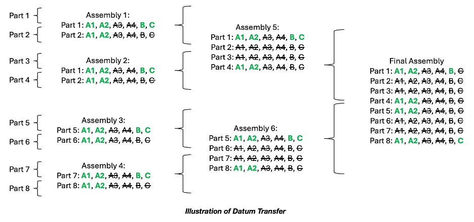
Typically, to control six degrees of freedom, a minimum of three datum features need to be defined, whereby the datum controlling the most degrees of freedom is denoted first using the letter ‘A’ followed by ‘B’ and ‘C’ for the secondary and tertiary datums.
Additional letters are then used to denote where local control is required of non-rigid parts, or for sub-datum schemes used for localized assemblies, which will be discussed further in Part II.

As you move through the process, it is impossible to maintain all the individual part datum features, as the downstream sub-assemblies would simply have too many. Instead, only a subset of datum features is maintained, those that are physically accessible and traceable back to upstream processes.
Adding in new datum features breaks the logic of the production sequence, and processes will no longer talk to each other.
What this means is, if you defined the coordinate system on an assembly using one set of datums, and then abandoning them for another set later. The results from the first coordinate frame, will have no relation to the second coordinate frame making it extremely difficult to debug your manufacturing process as you commission and ramp production.
🧮 Get Ready for Part II
Once you have done all these things, you are ready for the tolerance stack. But just like a Substack article, a tolerance stack should not be too long, and so you will have to wait until part II! In this article, we will move from tolerance stack through to the following activities that need to be done to make your product manufacturable.
📚Thanks for Reading
If you enjoyed the article please consider sharing or subscribing. If you are not yet convinced please check out some of my other articles:
Also, please feel free to connect with me on LinkedIn.
Lovely piece, Glen Turley
Nicely brings out the nuances between design specs and manufacturing fitment -and the unseen compromises many times required in an imperfect world.